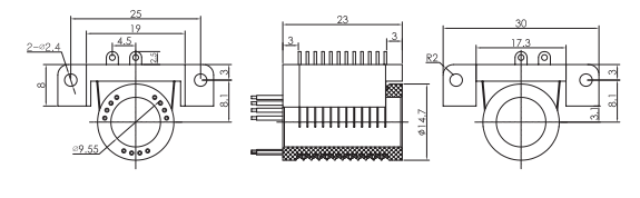
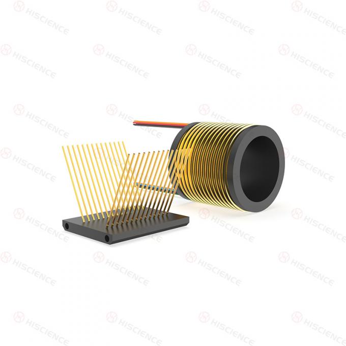
The HLS010-12 Separate Slip Ring consists of an independent rotor and brush assembly. Compared with conventional integrated slip rings, the separated structure provides greater flexibility for equipment layout and installation.
The rotor section can be designed with a through-bore for hydraulic channels, pneumatic channels, or drive shaft mounting, allowing better adaptation to space constraints and specific installation requirements.
This model is configured with 12 circuits and is suitable for compact precision instruments, rotary systems, industrial equipment, and applications requiring reliable signal or power transmission in limited mounting space. Its separated rotor and brush block structure helps save installation space, reduce overall weight, and improve integration flexibility.
| Item | Specification |
|---|---|
| Product Type | Separate Slip Ring |
| Model | HLS010-12 |
| Circuits | 12 circuits |
| Working Temperature | -40°C ~ 80°C |
| Working Humidity | 0 ~ 85%RH |
| Working Speed | 0–300RPM |
| Contact Material | Precious Metal |
| Insulation Resistance | ≥500MΩ@500VDC |
| Structure | Independent rotor and brush assembly |
| Custom Options | Through-bore size, connector type, wire length, working speed |

To select a suitable separate slip ring, please confirm the following information:
Number of circuits
Current and voltage requirements
Signal type or power transmission requirements
Through-bore size or solid shaft requirement
Rotor and brush block installation space
Mounting method and equipment structure
Working speed
Working temperature and humidity
Wire length or connector requirements
Whether hydraulic, pneumatic, or drive shaft integration is required
If you are not sure which model is suitable, please send us your installation space, circuit number, current rating, and application details. Our engineers can recommend a suitable separate slip ring solution based on your requirements.
Separated rotor and brush block design helps solve installation space constraints
12-circuit design suitable for compact rotating equipment
Rotor and stator can be installed independently
Through-bore sizes available from 9.5 mm to 100 mm, with solid shaft options available
Compact structure helps reduce overall equipment weight
V-groove gold-plated ring design offers excellent oxidation resistance and wear resistance
Precious metal contacts support stable and reliable transmission performance
Suitable for compact precision instruments and small equipment
Customizable structure for different installation and transmission needs
| Application | Typical Use |
|---|---|
| Industrial Machining Centers | Used in compact rotating systems requiring flexible installation |
| Rotary Tables | Transfers power or signals between rotating and stationary parts |
| Heavy Equipment Turrets | Suitable for rotating structures with limited installation space |
| Cable Reels | Maintains electrical connection during winding and rotation |
| Packaging Equipment | Supports rotating mechanisms in automated production lines |
| Magnetic Clutches | Used in compact rotating transmission systems |
| Process Control Equipment | Supports stable transmission in process automation systems |
| Rotary Sensors | Used for signal transmission between rotating and fixed parts |
| Emergency Lighting Equipment | Suitable for rotating or moving electrical assemblies |
| Robots / Exhibition / Display Equipment | Supports rotating display platforms and robotic systems |
| Medical Equipment | Suitable for compact medical or precision rotating equipment |
| Revolving Doors | Provides continuous electrical transmission in rotating structures |
Through-bore size
Current capacity
Voltage rating
Working temperature
Working speed
Connector type
Wire length
Installation structure
Solid shaft or through-bore design
Rotor and brush block configuration
If the standard HLS010-12 model does not fully meet your requirements, please send us your application details, including circuit number, current, voltage, installation space, mounting method, working speed, and operating environment.
Our engineers can help confirm the suitable model or provide a customized separate slip ring solution according to your equipment requirements.
Get a Quote
Download Datasheet
Request Drawing / 3D Model