选择语言

A fiber optic slip ring is worth considering when a rotating system must transfer optical data continuously between stationary and rotating parts. It is especially relevant when an application requires high-bandwidth communication, stable optical transmission, or reliable data transfer in an environment with electromagnetic interference. The right choice depends on the optical link, mechanical layout, rotation conditions, and whether electrical power or signals must also pass through the assembly.
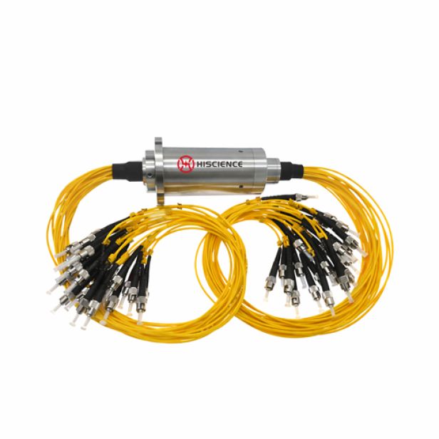
What Does a Fiber Optic Slip Ring Do?
A fiber optic slip ring, also called a fiber optic rotary joint (FORJ), enables optical signals to pass between stationary and rotating components while allowing continuous rotation. Unlike a conventional electrical slip ring, which transfers electrical power or signals through conductive contacts, a fiber optic slip ring transfers optical signals through an optical path.
For systems that need both optical data and electrical power or control signals, an optical-electrical integrated slip ring may be considered. This combines optical transmission with electrical channels in one rotary assembly, subject to the application’s specifications.
When Should You Consider a Fiber Optic Slip Ring?
1. The System Requires High-Bandwidth Data Transmission
Consider fiber optic transmission when a rotating system carries data-intensive information, such as high-resolution video, imaging data, or large data streams. The required data rate and interface should be confirmed with the equipment or network design before selecting a model.
2. Electromagnetic Interference Is a Concern
Optical signal transmission is not susceptible to electromagnetic interference in the same way as electrical signal transmission. A fiber optic slip ring can therefore be useful near motors, drives, power equipment, or other sources of electrical noise, provided the complete system is designed and installed appropriately.
3. Optical Communication Must Continue During Rotation
If cameras, sensors, communication devices, or other equipment are mounted on a rotating platform, a fiber optic slip ring can maintain an optical communication path between the rotating and stationary sides. It is particularly relevant where continuous rotation is part of normal operation.
4. The Application Uses Optical Links or Fiber Networks
When the equipment already uses fiber-optic communication, an optical rotary joint can help maintain the optical link across a rotating interface. Confirm the fiber type, wavelength, connector interface, and optical performance requirements to ensure compatibility with the existing system.
5. The Equipment Needs Optical and Electrical Transmission Together
Some applications require optical data as well as electrical power, control signals, or other electrical channels. In these cases, an optical-electrical integrated slip ring may reduce the need for separate rotary transmission components. The required electrical circuits and optical channels should be specified independently.
Typical Applications
l Fiber optic slip rings may be considered for applications such as:
l Radar and antenna systems that require optical data transmission during rotation.
l Surveillance and imaging equipment with rotating cameras or high-resolution video links.
l Industrial automation systems that exchange data across rotating equipment.
l Communication equipment using fiber-optic links across a rotating interface.
l Robotics or specialized machinery that requires optical transmission, with or without integrated electrical channels.
What Should Be Confirmed Before Selection?
Category |
Required Information |
Optical transmission |
Single-mode or multimode fiber; wavelength; number of optical channels; required data / interface |
Optical performance |
Permissible insertion loss and fluctuation; return loss requirements if applicable |
Connection |
Connector type and end-face / polishing requirements, if specified |
Mechanical |
Available installation space; mounting arrangement; shaft or bore requirements if applicable |
Motion |
Rotational speed; continuous or intermittent rotation; rotation direction if relevant |
Environment |
Operating temperature; dust, moisture, vibration and protection requirements |
Electrical integration |
Whether power, control signals, Ethernet, RF or other electrical channels are also needed |
Documentation |
System diagram, fiber link specifications, mechanical drawing, or application description |
Actual limits vary by model. Confirm the required parameters against the selected product’s datasheet rather than assuming that every fiber optic slip ring supports the same fiber type, wavelength, speed, connector, or environmental rating.
HISCIENCE Fiber Optic Slip Ring Solutions
Hiscience offers single-channel and multi-channel fiber optic slip ring series, as well as optical-electrical integrated slip ring solutions. These options can be evaluated according to the required optical channels, optical interface, installation conditions, and whether electrical transmission must be combined in the same assembly.
Learn more about the Hiscience Fiber Optic Slip Ring Series
Need Help Choosing a Fiber Optic Slip Ring??
If you are not sure which configuration is suitable, provide:
fiber type + wavelength + number of optical channels + connector type + optical performance requirements + rotational speed + installation space + operating environment
Contact Hiscience for a technical review.
Tel:+86-13543318795
+86-0755-23200548
Email:sales@hslipring.com
WhatsApp:+8613543318795
WeChat:13543318795
Address:3rd Floor, Building 1, Hengchangrong High-tech Industrial Park, No.128 Shangnan East Road, Shajing Subdistrict, Bao'an District, Shenzhen City