选择语言

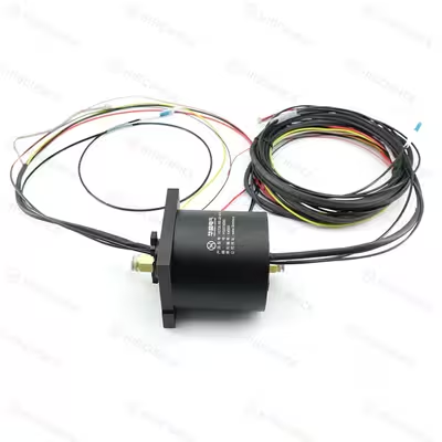
Description
The fiber optic slip ring, also known as an optical slip ring, is aspecialized rotating connector designed to facilitate uninterrupted 360° rotation and transmission of optical energy and signals. It enables seamless fiber optic signal transmission between rotating and stationary components, making it ideal for applications requiring high-speed signals, large information capacity, high precision, and long-distance transmission. Unlike traditional slip rings, the optical signal transmission in a fiber optic slip ring is non-contact and non-frictional, ensuring a lifespan of up to hundreds of millions of rotations. The fully sealed design guarantees independent transmission of optical signals, free from interference with electrical signals and immune to electromagnetic interference. This design feature provides robust adaptability to challenging application environments, including low temperatures, high pressures, and electromagnetic interference. When paired with an electric slip ring, the fiber optic slip ring forms a Fiber-Electric Slip Ring system capable of transmitting both power and high-speed data simultaneously, offering versatile solutions for complex industrial and technological requirements.
Specifications
Circuits/Current: 3*20A + 2*5A+shield
Voltage: 0-380VAC/DC
Lead Wire size: AWG14# / AWG 22#
Dielectric strength: ≥500V@50Hz
Insulation Resistance: 500MΩ@500VDC
Dynamic Contact Resistance: ≤10mΩ
Working Speed: 0-200RPM
Protection(lP Grade): IP51
Working Temperature: -30℃~+70°C
Contact Material: Precious Metal
Housing Material: Aluminum Alloy
Passages: 1 Passage
Connection Thread Size: 1/4, 10mm
Pressure: ≤1 Mpa
Transmitting Media: Compressed Air
Fiber Types SM: 9/125um
Channel number: 1
Wavelength range SM: 1310/1550nm
Insertion loss:<2dB
Connector types : LC(UPC)
Features
Hiscience's fiber optic slip ring incorporates patented optical coupling technology, offering significant advantages:Patented Optical Coupling Technology: Self-developed with simplified coupling process—no fiber collimators or coaxial adjustment needed. One-time assembly with efficiency over 10 times higher than market counterparts, ensuring a 100% pass-through rate.
Long Service Life: Supports 200-400 million rotations
Original Low-Loss Optical Coupling Technology: Ensures minimal signal loss
Sealed Structure: Optical components remain unaffected by external environment factors
Compact and Lightweight: Facilitates easy integration with electrical slip rings
No Leakage, No Electromagnetic Interference: Suitable for long-distance transmission (tens to hundreds of kilometers)
High Bandwidth Transmission: Offers significantly larger transmission bandwidth than electrical connectors. Compatible with wavelength division multiplexers for enhanced bandwidth utilization.
Main Applications
Robots
Material Handling Systems
Medical Systems
Remote Control Systems
Radar Systems
Rotating Turrets on Vehicles
Video Surveillance Systems
Offshore Equipment
Naval Systems
National or International Security Systems
Submarine Operations Systems
Customizable Options
1、Service Life: Single Mode ≥ 200 million rotations (300 RPM); Multi Mode ≥ 100 million rotations (300 RPM)
2、Fiber Transmission Types: Various options available
3、Power and Signal Configurations: Number and types are customizable
4、Fiber Type: Options include single-mode or multi-mode, single-channel or multi-channel configurations
5、Customization: Shape, shell material, and drive connector are customizable
6、Fiber Connectors: Optional types such as FC, LC, PC, ST, etc